Home Línea de corte y aplanado de chapa metálica Línea de corte y aplanado de chapa metálica - Online auction
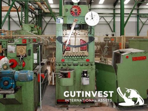
ObservationsSheet Metal Cut-to-Length and Flattening Line
Composed of:
Decoiler, entry and pre-straightening group, leveler, drive group, loop table, shear, measuring table, stacking table, and exit rollers.
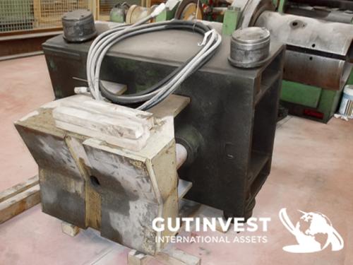
DECOILER
Mounted on a welded steel frame designed to support the coil in the working position. It consists of a mandrel supported on bearings and equipped with a hydraulically actuated concentric expansion device.
The rotation is driven by the traction exerted on the strip by the leveler. It includes a pneumatic brake to keep the strip under correct tension for centering with the leveler.
It has a loading car for inserting the coil onto the mandrel. This car is mounted over a pit, and both its lifting and translation are hydraulic.
SPECIFICATIONS
·Maximum coil weight: 5,000 kg
·Maximum strip width: 650 mm
·Approx. maximum outside coil Ø: 1,500 mm
·Maximum mandrel Ø (expanded): 520 mm
·Minimum mandrel Ø (collapsed): 480 mm
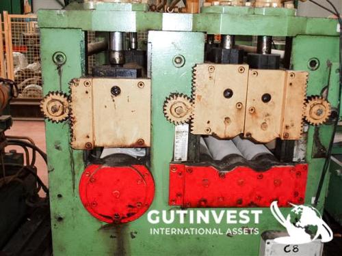
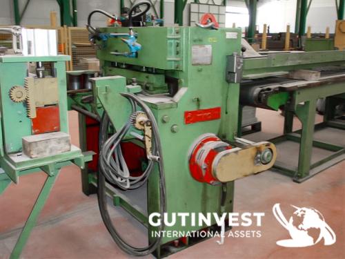
ENTRY AND PRE-STRAIGHTENING GROUP
Made up of a welded steel structure that supports both the entry rollers and the pre-straightening rollers, as well as the motor and gearbox.
The two entry rollers are rubber-vulcanized and ground for greater grip when feeding the strip into the leveler. The upper roller is actuated vertically by two hydraulic cylinders that apply pressure during feeding.
The pre-straightening rollers perform an initial straightening—especially on thicker gauges—for improved final leveling by the leveler. They consist of five rollers: three lower and two upper.
The two upper rollers are each actuated independently by two hydraulic cylinders that apply pressure to the strip for pre-leveling before it enters the leveler.
The pre-straightening rollers are made of non-deformable F-521 steel, heat-treated and ground.
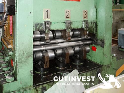
LEVELER
DESCRIPTION
The leveler is divided into three parts:
1.Leveling group
2.Drive group for the 17 leveling rollers
3.Drives
Leveling group
Welded steel frame designed to withstand the pressures applied to the lower rollers—nine rollers in this case. These rollers, in turn, are supported by three rows of backup rollers which, via independent screws, control the deflection of the lower rollers for correct leveling. The backup rollers operate mechanically.
The upper rollers—eight in this case—are supported by the upper body of the frame. This body is driven vertically by two screws and their corresponding gearmotor to achieve penetration into the strip for proper leveling.
The body supporting the upper rollers can be tilted in the strip travel direction to apply more pressure at the entry side. This operation is also performed by its gearmotor and controlled electrically.
Both the upper and lower rollers are made of F-521 steel, heat-treated and ground.
DRIVE GROUP
Consists of a welded steel housing that contains the reducer elements for driving the leveler rollers. This housing has 17 outputs to couple the transmissions that rotate the leveler rollers—one for each roller, upper and lower.
Both the reducer housing and the leveler rollers are driven by a DC motor with a speed controller, allowing automatic adjustment of machine speed to suit the leveling requirements, strip quality, and material thickness being processed.
Specifications:
·Motor power: ASEA. INDER — LAK 200 LA, 35 kW
·Speed controller: TT-12-50 bidirectional three-phase controller
·Reducer: PUYOL KX 603/6.48
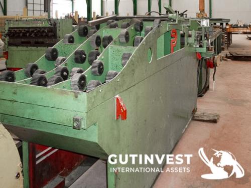
LOOP TABLE
Composed of a welded steel structure forming a loop and star-shaped, knurled rubber wheels, allowing the strip to slide properly during automatic operation and, at the same time, to accumulate material in front of the shear when the strip stops for cutting.
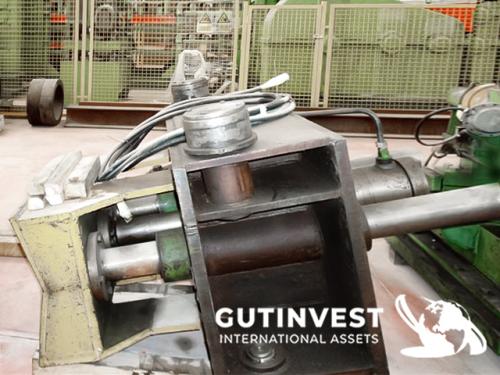
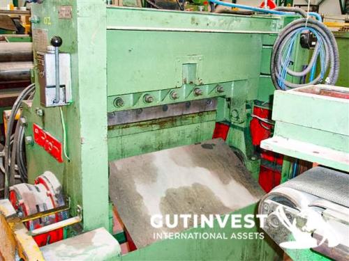
SHEAR
A welded steel base supports the bridge and both upper and lower knife holders, the shaft that drives the cutting connecting rods, and the electro-pneumatic clutch that actuates the strip cut. The knives are distance-adjustable via a mechanical control to adapt to different strip thicknesses.
MEASURING TABLE
A welded steel structure on which two independent belts are mounted to evacuate the cut strip to the stacking area.
It also carries a carriage containing all pneumatic and mechanical accessories for the measuring process. The cut length is set by a mechanical control using a rack and handwheel.
STACKING TABLE AND EXIT ROLLERS
A welded steel structure that supports both the side plates and the length stop carriage for forming the package.
The exit rollers are arranged on two independent tables, one of which is height-adjustable via reducers and screws. This entire process operates automatically without operator intervention.
Once the package is formed, the two tables are set to the same height to transfer the finished pack to the second table, where it can be strapped and evacuated without having to stop the line’s production.
No. of items: 1
Recomended lots
Confirm your maximum bid
Confirm your maximum bid
Loading…
Conecting
Are you sure you want to buy the lot?